Once-through boilers have forced circulation because a pump forces water through the generator tubes;
because the water goes through in one pass, they have no recirculation. Natural circulation is brought
about by differences in density caused by heating and usually involves repeatedly circulating the water
through the coils because a single pass is insufficient to convert all the water into steam; the water
recirculates but the recirculation is not forced.
A smaller and lighter boiler can be obtained by aggressively forcing water recirculation with a pump,
this guaranteeing circulation rates high enough to avoid DNB and permitting harder firing with greater
steam production. ‘Forced recirculation boilers’ may provide reserve capability similar to a fire tube
boiler by circulating water to and from a storage drum, the drum also permits contaminants to settle out
without causing harmful deposits on the tube walls. The drum and pump ensure the tubes are always
flooded and the surface areas devoted to generating and superheating steam are of fixed size, control is
simpler than a monotube with the feed water admission rate controlled by the drum level and the firing
rate controlled by the steam pressure. Potential drawbacks include extra weight, cost, maintenance and
whatever reliability issues are associated with the pump. Although forced recirculation boilers long
preceded him, Walter Douglas LaMont championed and developed the concept like no one before and as
a class they are generally referred to as LaMont boilers.
LaMont boilers are very rare in steam automobiles, a strange oversight given the potential for high
performance. The abortive French-Coats automobile used a variety of forced recirculation while the
experimental International Harvester tractor used a jet pump to accelerate recirculation, as did the
production Toledo steamer of 1900 and a few others. Steam car enthusiasts are currently giving forced
recirculation a second look and mostly like what they are seeing; more than one planned or ongoing
home build project boasts a forced recirculation boiler, making the concept worth discussing here.
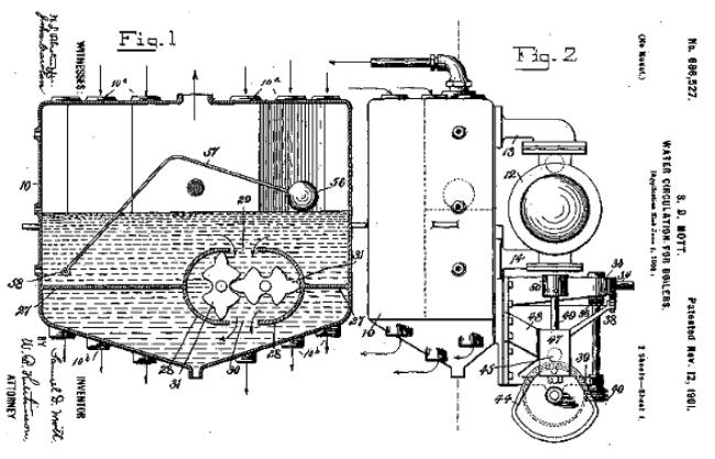
The water drum (cross section, left)
comprises two chambers; the upper
holds the water/steam mix while the
lower is water filled. Tubes
connecting the chambers extend
from the bottom of the lower to the
top of the upper and pass through
the burner. A gear pump between
the chambers forces water from the
upper to the lower; displacing water
through the heated tubes with the
resulting steam/water mix arriving
in the upper chamber.
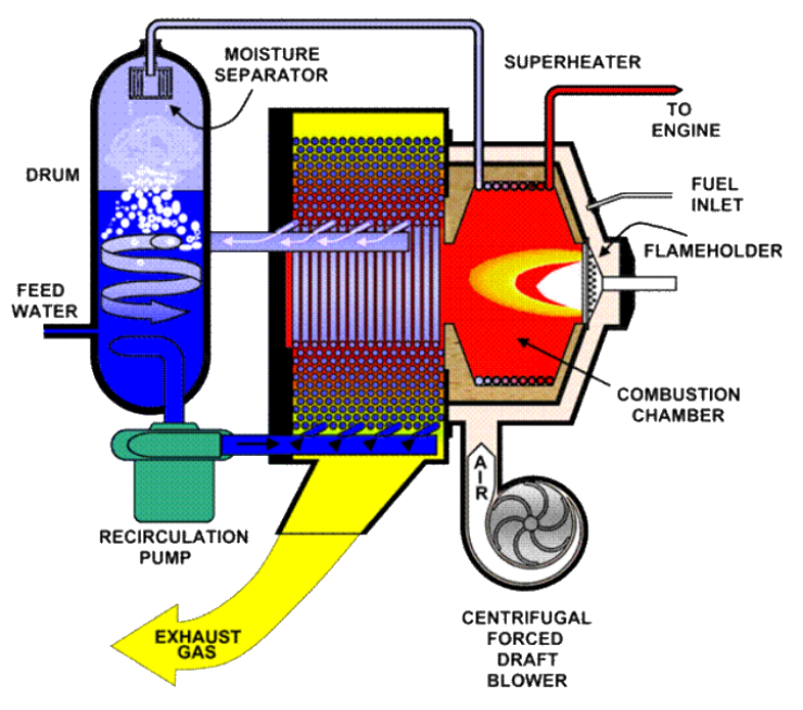
The drawing, below, illustrates a forced recirculation system. The pump (lower left) draws saturated
water from the drum, forcing it through the bottom manifold and into the parallel coils. Spiraling
inwards towards the central fire, the steam/water in each tube reaches the inner manifold and reunites.
The combined flow re-enters the drum at a swirl-inducing tangent, the velocity now being faster than at
the pump due to the increase in volume caused by heating. Centrifugal force drives the heavier water
component outwards to the drum wall, where it descends, while the lighter steam component moves
inwards and rises. The water enters the pump suction at another tangent, converting the water velocity
into a pressure head that assists the pump. The steam rises above the water surface, passes a separator
composed of a labyrinthine passage designed to remove entrained water and then passes out of the drum
to a superheater coil in the fire box and then onto the engine.
Combustion starts with a centrifugal fan (lower right) supplying forced draft to an annular housing
surrounding the combustion chamber, the air absorbs heat emanating from the chamber and entering the
chamber returns it, improving economy. Fuel sprayed into the air just prior to the flame holder
guarantees a good mix and, through evaporation, wicks off heat potentially harmful to the flame holder.
The fuel/air mix passes through the flame holder and ignites, producing an intense flame which
superheats steam in the coils encircling the combustion chamber, absorbing this heat they in turn protect
the chamber walls. Hot combustion gasses flow outwards around the tubes of the coil stack where the
outer shell directs them to the exhaust duct at the bottom.
LAMONT
(FORCED RECIRCULATION)