Valve gears modify the valve motion to change cutoff or
reverse the engine, the sliding eccentric being among the
simplest types.
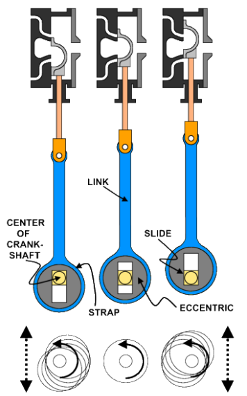
An eccentric pierced by a rectangular slot resides on, and is
revolved by, a square extension of the crankshaft. A
mechanism (not shown) slides the eccentric perpendicular to
the square shaft, changing the orientation and eccentricity.
The amount of cutoff and direction of engine rotation is
regulated by the orientation and magnitude of eccentricity:
The left view shows the engine in forward motion, the
eccentric is in the low position with the valve admitting
steam to cylinder top half and exhausting the bottom.
The center view shows the engine in neutral, the
eccentric is coaxial with crank valve and the valve
blocks flow to and from the cylinder.
The right view shows the engine in reverse, the
eccentric is in the high position with the valve
exhausting the cylinder top half and admitting
steam to bottom.
The sketches at the bottom of the drawing illustrate the
motion of the eccentric as the crankshaft revolves.
Increasing eccentricity increases overall motion and amount
of cutoff.
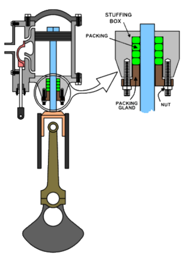


 Packing minimizes the escape of steam along the
piston and valve rods. Traditional packing
materials are square woven sections of mixed
cotton, flax, asbestos, hemp or other fiber soaked in
an oleaginous (greasy) substance to limit friction.
Graphite and mica often serve as friction reducing
additives and sometimes brass discs are added for
stability. The piston or valve rod passes out of the
engine via a chamber called the stuffing box; the
packing is wound around the shaft and compressed
against the shaft and stuffing box walls by a
packing gland to form a sliding seal. Modern
packing materials include Teflon, carbon filament,
bearing metals as babbit, Kevlar and flurosilicones.
Simple, Double Acting, Slide Valve Steam Engine, page 2
The animation illustrates the pressure and temperature throughout a stroke for a traditional steam
engine. While DA engines produce power when the piston moves in both directions, we will keep
matters simple only showing the flow to and from the left hand side of the cylinder. The “D” valve
(top center) directs hot steam to the cylinder and cuts it off at about ¼ stroke (red) and directs cold
low pressure steam from the cylinder to the exhaust port (blue). The gage (at left) records cylinder
pressure and color indicates steam temperature, red being hot and blue cool with various shades
showing intermediate temperatures. A device using very similar principles was used to produce
graphs much like those that illustrated Mean Effective Pressure on the last page. The moving dot
following the piston indicates cylinder volume and pressure at any given point in the stroke.
The events in a steam engine expansion cycle, starting at the top left and traveling clockwise, are:
ADMISSION. Hot and pressurized steam enters the cylinder and gives up some energy by working
against the piston; pressure and temperature do not drop significantly because more steam directly
from the boiler enters through the valve.
EXPANSION. Cutting off the steam flow into the cylinder causes the temperature and pressure to
drop steadily as the steam energy is transferred to the piston, which in turn causes the engine to
produce power. Delaying cutoff allows more steam into the cylinder, increasing power but reducing
expansion; steam pressure and temperature fall less, indicating the engine is extracting energy from
the steam less efficiently.
RELEASE. Pressure and temperature plunge as the valve opens, allowing cylinder contents to exit the
cylinder.
EXHAUST. The valve allows the cylinder contents to continue exiting the cylinder as the piston
returns to the beginning of the stroke, pressure and temperature stay low.
COMPRESSION. The valve closes, trapping a small amount of steam in the cylinder. The continued
progression of the piston packs the steam into a small volume, raising temperature and pressure.
Packing minimizes the escape of steam along the
piston and valve rods. Traditional packing
materials are square woven sections of mixed
cotton, flax, asbestos, hemp or other fiber soaked in
an oleaginous (greasy) substance to limit friction.
Graphite and mica often serve as friction reducing
additives and sometimes brass discs are added for
stability. The piston or valve rod passes out of the
engine via a chamber called the stuffing box; the
packing is wound around the shaft and compressed
against the shaft and stuffing box walls by a
packing gland to form a sliding seal. Modern
packing materials include Teflon, carbon filament,
bearing metals as babbit, Kevlar and flurosilicones.
Simple, Double Acting, Slide Valve Steam Engine, page 2
The animation illustrates the pressure and temperature throughout a stroke for a traditional steam
engine. While DA engines produce power when the piston moves in both directions, we will keep
matters simple only showing the flow to and from the left hand side of the cylinder. The “D” valve
(top center) directs hot steam to the cylinder and cuts it off at about ¼ stroke (red) and directs cold
low pressure steam from the cylinder to the exhaust port (blue). The gage (at left) records cylinder
pressure and color indicates steam temperature, red being hot and blue cool with various shades
showing intermediate temperatures. A device using very similar principles was used to produce
graphs much like those that illustrated Mean Effective Pressure on the last page. The moving dot
following the piston indicates cylinder volume and pressure at any given point in the stroke.
The events in a steam engine expansion cycle, starting at the top left and traveling clockwise, are:
ADMISSION. Hot and pressurized steam enters the cylinder and gives up some energy by working
against the piston; pressure and temperature do not drop significantly because more steam directly
from the boiler enters through the valve.
EXPANSION. Cutting off the steam flow into the cylinder causes the temperature and pressure to
drop steadily as the steam energy is transferred to the piston, which in turn causes the engine to
produce power. Delaying cutoff allows more steam into the cylinder, increasing power but reducing
expansion; steam pressure and temperature fall less, indicating the engine is extracting energy from
the steam less efficiently.
RELEASE. Pressure and temperature plunge as the valve opens, allowing cylinder contents to exit the
cylinder.
EXHAUST. The valve allows the cylinder contents to continue exiting the cylinder as the piston
returns to the beginning of the stroke, pressure and temperature stay low.
COMPRESSION. The valve closes, trapping a small amount of steam in the cylinder. The continued
progression of the piston packs the steam into a small volume, raising temperature and pressure.