THE STEAM
POWER
CYCLE,
a brief overview
The feed phase is straightforward; water drawn from the condenser or storage tank is pumped under
pressure into the boiler. Larger powerplants have multi-stage centrifugal feed pumps but piston pumps
are more practical in automotive sized power plants.
An almost bewildering variety of piston pumps have been used over the years:
Single and double acting.
Simple and compound.
Single and multiple cylinders, inline and radial layout.
Powered by the driver or passenger pulling a lever, directly by the engine,
with an electric motor, a built-in steam cylinder…
Flow rate controlled by varying the stroke, deactivating valves, pressure
relief devices
And so on….
For all this diversity, the basic operating principles are nearly always the same; a reciprocating piston or
ram causes the volume inside the pump body to fluctuate, alternately drawing and expelling a fluid
while check valves direct the flow accordingly.
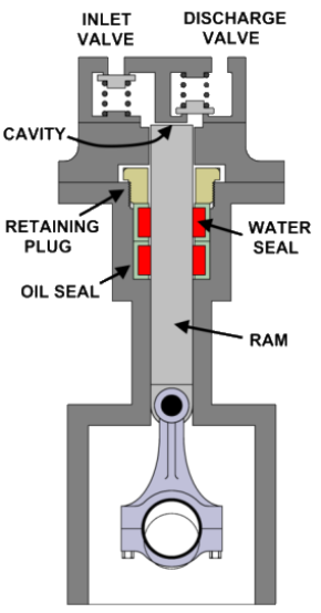
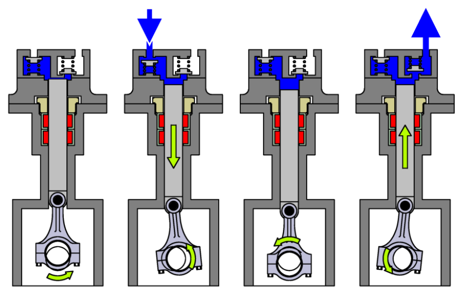
A common variety of high-pressure pump is found in
pressure washers. To the left we see that the crankshaft and
connecting rod reciprocate the ram in a closely fitting
cylinder lubricated by oil from the crankcase while the
upper portion of the ram reciprocates in a cavity without
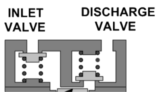
touching the sidewalls. Check valves in the cylinder head,
shown in close up at right, are discs held against their seats
by springs and permit water to flow in one direction. The
two seals separate the water in the upper pump end from the
oil in the crankcase.
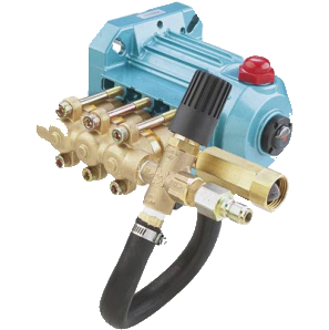
Pressure washer pumps are readily available
in a number of sizes and pressure ranges for a
few hundred dollars, a simple and effective
solution for an automotive feed pump.
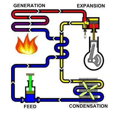
Note how the feed water and engine exhaust flow paths
intertwine in the drawing at left, representing the action
of the feed water heater. As you recall, heat rejected to
the environment by the condenser is lost from the system
and reduces overall efficiency. The feed water heater
reduces these losses by transferring some heat energy
directly from the exhaust steam to the feed water.
Feed heaters also come in all manner of shapes and
sizes, mostly in a “shell and tube” design wherein a shell
encapsulates one or more tubes with fluid flowing in the
tube interior(s). A second fluid is pumped through the
shell and is free to circulate around the tube interiors,
with heat transferring from one fluid to the other by
passing through the tube walls. If this sounds familiar,
it is how the Stanley fire tube boiler functions with hot
gasses being the fluid passing through the tubes. Such a
heat exchanger is shown at right, the shell being made
in two halves bolted together on a central flange while
the tube is a helical nest wound from the center
outwards.
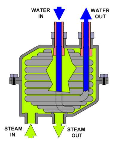

 As in boilers, the fluids flow in opposite directions to promote best heat transfer. The steam enters at
the outer edge of the shell and works past the tubes before entering out the center bottom. The steam
enters the tube from the center and spirals outwards, departing at the rim.
One would assume finned tube construction due to the lower steam density and conductivity, but this is
rarely the case. The amount of heat transferred by the feed heater is not relatively great and the space
and weight savings finned tube could provide are not that significant.
One potential difficulty arises if the water temperature in the condenser is too high, the pressure drop
at the pump suction can partially flash this boiler feed water into steam, the resulting vapor lock
preventing feed water from reaching the boiler, a condition that can sometimes harm the pump not to
mention overheat the boiler and cause serious damage or destruction. Should vapor lock be a
problem, a very mild booster pump with low suction and discharge pressure can be added, the suction
pressure is low enough to avoid vapor lock and the discharge pressure is high enough that the feed can
no longer flash in the feed pump inlet.
As in boilers, the fluids flow in opposite directions to promote best heat transfer. The steam enters at
the outer edge of the shell and works past the tubes before entering out the center bottom. The steam
enters the tube from the center and spirals outwards, departing at the rim.
One would assume finned tube construction due to the lower steam density and conductivity, but this is
rarely the case. The amount of heat transferred by the feed heater is not relatively great and the space
and weight savings finned tube could provide are not that significant.
One potential difficulty arises if the water temperature in the condenser is too high, the pressure drop
at the pump suction can partially flash this boiler feed water into steam, the resulting vapor lock
preventing feed water from reaching the boiler, a condition that can sometimes harm the pump not to
mention overheat the boiler and cause serious damage or destruction. Should vapor lock be a
problem, a very mild booster pump with low suction and discharge pressure can be added, the suction
pressure is low enough to avoid vapor lock and the discharge pressure is high enough that the feed can
no longer flash in the feed pump inlet.