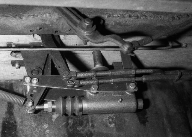
Master cylinder in place under floor board.
SOME NOTES ON FITTING FOUR WHEEL BRAKES TO STANLEY CONDENSING CARS
Two principles are followed in this design. First, as much of the existing Stanley structure as possible is used. And, irreversable changes are kept to an absolute minimum. In fact, the only such changes are small holes in the floor boards and frame and modifications to the front hubs to fit the brake drums. A spare set of Stanley model 735 drums were used.
In the standard Stanley condensing car brakes, the braking torque is handled by the engine and hanger strap and the braking force is transferred to the front axle and springs through the reach rods. In the four wheel design, the rear axle forces are unchanged and the front axle forces are carried by the front spring. Some of the front axle torque is absorbed by bending forces on the reach rods. No difficulties with this arrangement have been found in more than 5000 miles of touring.
As Stanley drums are steel pressings, and not all the same size, flexible brake shoes are used. Thus, the need to make shoes to match a specific drum is avoided. To avoid possible lock-up or serious fading problems, the Bendix servo brake scheme is not used. Instead, one leading and one trailing shoe are used in each drum. The linings are a "soft" type bonded to the shoes by a truck brake and spring service company, and are rated for 350 deg. F. continuous or 650 deg. intermittent duty.
Standard "Raybestos" cylinders and fittings were selected, the criteria being ease of mounting and the largest size that would fit in the drums. The master cylinder and wheel cylinders all have the same bore, 1 1/8 inches. The parts used are:
Master cylinder MC 36483
Adapter bushing H 8028
Rear wheel cylinder WC 36057
WC 36058
Rear hose BH 38871
Front wheel cylinder WC 24954
WC 24955
Front hoses (2) BH 10304
Not listed are the 3/16 hydraulic lines and fittings.
The master cylinder is mounted under the floor with a bracket one end of which is bolted to the existing brake pedal bracket. As a result, an extended fill tube, going through the floor and fitted with a dip stick must be used. The bracket and actuating lever were designed for two possible cylinder mountings. The lower position makes the maximum pedal travel produce the maximum possible piston stroke. The higher position gives 1 1/2 times the leverage with 2/3 the stroke. The lower location has proved to be the better.
Master cylinder in place under floor board.
The actuating lever is bolted to the existing clevis pin hole on the Stanley brake pedal and filed to fit the fulcrum boss. It is stiffened by bolting a 7/16 thick spacer between the two plates near the fulcrum. The master cylinder clevis bolt has a grooved extension for the return spring.
At the rear axle, the normal Stanley bands and running brake parts are removed, leaving the emergency brake cams and linkage in place. The adjusters of the new brake shoes rest on these cams, so the emergency brake is fully functional.
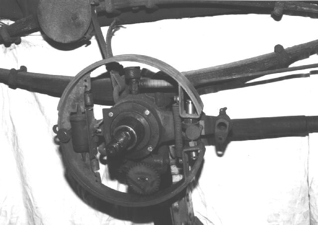
Rear axle with new brakes and speedometer drive.
Extra long king pins are fitted to the Timken front axle to provide mounting for the brake "back" plate. The king pin is keyed to the steering knuckle, and, being an inch in diameter, is eminently strong. It is drilled to enable greasing the bushes through fittings on the inner plate mounting blocks, as there is very little clearance between the ends of the pin and the brake shoes. (Another reason for using flexible shoes!) The mounting blocks must be made to match the camber angle between the king pin and the wheel spindle and the location of the brake drum when it is mounted on the wheel hub. Be sure to check for clearance between the drum and the tie rod pitman arms before making the blocks, shimming the wheel bearings may be necessary.
The front brake "back" plates are inside out to avoid interference with the existing knuckle structure. The cylinder bracket should be mounted with flat head screws, as there must be clearance for the drum mounting bolts. The "rest pin" is 1/2 inch diameter by 1 1/2 long, drilled and tapped for 1/4-28 bolts. 1/8 thick washers with beveled edges are fitted at each end to center the shoes axially. The "torque pins" are 11/16 diameter by 1 1/2 long drilled and tapped for 7/16-20 bolts. The mounting bolts for the torque pin bracket should be larger than shown, 7/16-20 is suggested.
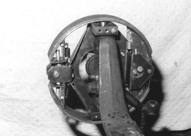
Right end of front axle, photographed during initial assembly.
The brake hoses in the list for the front axle are not very long so the location of the chassis end must be carefully chosen. Check for free movement from lock to lock with the axle hanging on the springs. (Support chassis on stands.)
The 1/2-20 adjuster, suggested in the shoe drawing and shown in some of the photos, proved marginal in strength and nearly impossible to adjust in the rear axle. Therefore, 3/4-16 adjusters have been made and fitted, and are recommended. They also proved to be easier to adjust, being drilled for a "pin" wrench in eight places instead of the six in the old adjusters.
It will be necessary to adjust the brakes several times in the first 500 miles as the shoes bed themselves in. After that, once per season will be found adequate unless one indulges in alpine touring. The upper shoes will wear more rapidly than the lower ones as they are the leading shoes while moving forward. However, the shoes are identical and can be "rotated" to equalize and extend wear. It appears that 5000 to 10,000 miles may be an appropriate interval.
The fitting of these brakes precludes the use of the existing front wheel speedometer drive. Coupling two cables enables driving from the rear axle. Two drive points are suggested, the generator drive or a gear mounted inside a rear drum. The photographs show the latter, using 12 pitch gears to reduce the size. The cable routing should be kept well clear of the main steam pipe to avoid frying the thin cable oil.
These brakes have been in use on my car for five years and have worked well. They have recently passed a very severe test; on August tenth 1999, I drove the car to the summit of Mount Washington and descended using these brakes as the sole control of the speed. I had fitted a shoe in the rear brake with a thermocouple to monitor brake heat, and at no time did the temperature exceed 300 deg. F. The descent was made at about ten miles per hour and three stops were made to rest my right leg as I feared the probable result of a muscle cramp. It appears that these brakes can continuously dissipate about ten horse power.
David K. Nergaard (revised 28 Aug. 2001)
Return to papers.