THE DIETER UNIFLOW STEAM ENGINE
By
Bruce Magnell
March 1999
Recently I acquired an interesting steam engine that was built by the Dieter Steam Engine Co. of New York, probably around 1900-1910. I brought this engine to the February 1999 meeting of SACA Northeast. The Dieter is a single-acting, high-pressure Uniflow engine, of advanced design for that period. The photo on the following page shows the engine as it appears now (photo by Rolle Evans), with a couple of the cylinder and valve access covers removed. The illustration on the next page is an advertisement (courtesy of Dave Nergaard) for the same engine, which appeared in the Steam Motor Journal in January 1908. This old advertisement shows an engine identical to the one I have, even down to the bronze cover plate with maker's name on the camshaft access port. Note the connection with August Ofeldt & Sons, makers of boilers and burners. Another ad linking Dieter and Ofeldt in the context of steam car applications is reproduced in Floyd Clymer's book (p. 71). Information on a 4-cylinder Dieter engine of similar design is given in the attached Appendix.
Mechanical Design
The 3-cylinder Dieter engine's mechanical dimensions are:
Dieter Steam Engine owned by Bruce Magnell, photographed at SACA Northeast meeting, February 1999 (Rolle Evans photo).
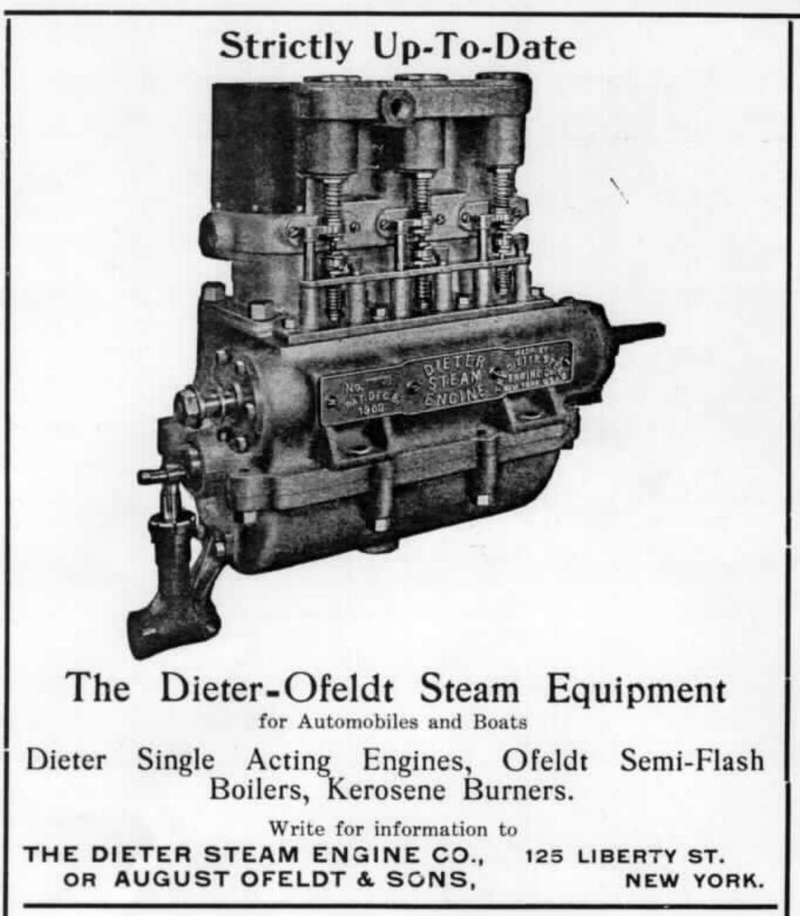
Advertisement for Dieter 3-cylinder engine in Steam Motor Journal, January 1908.
The engine has Uniflow exhaust ports, which are uncovered at the bottom of each stroke. The ports only cover part of the circumference, being located on each side facing the exhaust manifold. The cylinders are too close together to allow ports and manifolds between the cylinders. Also, the exhaust ports are fairly short, covering only 10% of the stroke. With this small port area, it is likely that the cylinders are inadequately vented at high speeds. For example, Prof. Stumpf (the guru of Uniflow design, who worked around the turn of the century) recommended 15% exhaust release and as much port area around the entire circumference of the cylinder as possible. Perhaps for this reason, and also to ensure smooth starting, Dieter equipped this engine with auxiliary exhaust poppet valves. These poppet valves operate at constant cutoff of 90%, independent of inlet valve events. As a result, the engine is really best described as "semi-uniflow" since there will be some counterflow of steam through the poppet exhaust valves on each cycle.
The engine is equipped with sleeve bearings throughout, and the bearing areas are not very large relative to the loads placed on them. The wrist pin bearings are the most heavily loaded, as usual. At maximum inlet pressure, the force on the piston will result in a wrist pin bearing pressure of 2180 psi at low speed. That is pretty high, suggesting that the engine would not have a long life if used very much at long cutoff and low speed. For the big end bearings, the maximum bearing pressure will be 923 psi, much better but still high. The main bearings will see only 285 psi max.
Performance
The expected performance of the Dieter is summarized below:
In summary, the Dieter engine is smaller in displacement than the 20 HP Stanley engine, but operates more efficiently in spite of its lower steam pressure, due to its ability to use short cutoff and highly superheated steam. The Dieter's 17.5 lb/hp-hr steam rate is not as good as the White (12 lb/hp-hr) or the Doble (10 lb/hp-hr). This is not surprising since those engines used higher temperatures and pressures, as well as compounding. For comparison, the White achieved a fuel rate of approximately 1 lb/hp-hr, while a modern gas engine gets 0.5 lb/hp-hr, and a diesel does best of all at 0.3 lb/hp-hr (estimates by Dave Nergaard).
Overall, the Dieter is a remarkably advanced work of engineering for its date. Some very capable people must have put a lot of effort into its design.
Steam Car Application
Can this engine be used to power a car? At first glance, it might seem that it could. In fact, one of the reasons I bought it was that it is very similar to the "Saab-Steamer" engine that Dave Nergaard, Hal Fuller, George Nutz and I designed and built around 1970 for the Clean Air Car Race. The Saab-Steamer was also a 3-cylinder, single-acting, short cutoff Uniflow engine with sliding camshaft, based on the 2-cycle, roller-bearing Saab automobile engine block. We built the engine, but never got around to the rest of the car, and then the engine was unfortunately damaged during testing.
A full-size car requires only about 20 HP to push it along at 60 mph on level ground, and in theory the Dieter could provide enough horsepower to do this. Modern cars, of course, are expected to cruise continuously at 80+ mph; at that speed the car would need about 50 HP. The Dieter obviously wouldn't provide enough continuous power to achieve that level of performance.
Even if we regard the horsepower as adequate, the engine would probably need a transmission if it were to be used in automotive service. The reason for this becomes clear when one considers acceleration. To operate at 60 mph with an engine speed of 600 RPM would require 36" diameter wheels, if direct drive with 1:1 axle gearing were employed. The engine's maximum 400 ft-lb of torque at low speed would then translate into 266 lbs of thrust at the wheels. (If smaller wheels are used, then step-up axle gearing would be needed, but the thrust available at the wheels would be the same). If the car weighed 3500 lb, the acceleration would be only 7.6% of gravity, or about 2.4 ft/sec2. At that rate, even if the engine and boiler could maintain the steam flow, and ignoring other power losses, 36 seconds would be required to get up to 60 mph! That's not exactly neck-snapping acceleration, and in fact such a car would be kind of a menace on modern roads. A heavier car would only make matters worse. A transmission would cure this problem, by permitting higher engine speeds at low ground speeds. A 4:1 step-down ratio would give excellent acceleration at low speeds, and it would allow a shorter cutoff to be used during acceleration, which would improve the fuel consumption, at the expense of a lot more weight and complexity. An intermediate gearing of about 2:1 would probably be required, as well.
A clutch would also be needed, to prevent the bearings from being damaged by applying maximum steam pressure at zero engine speed. The sleeve bearings are too small to survive much of that kind of service, so the engine would have to be turning at all times, even when starting from zero ground speed.
Another problem would be vibration. With only 3 single-acting cylinders, the Dieter's torque curve would be a bit lumpy at low speeds if directly geared to the axle. Doble complained that his 2-cylinder double-acting Uniflow engine was not smooth enough, and the Dieter would be worse. Again, a transmission would improve performance, since the torque variation wouldn't matter so much at higher engine speeds.
All in all, the Dieter's modest power capacity and vibration problems, combined with the need for both a variable-speed transmission and a clutch, makes this engine less than ideal for use in a modern steam car. So what did Dieter/Ofeldt have in mind? In 1900, of course, cars were lighter and weren't expected to go so fast. A 2000 lb car with a top speed of 30 mph would be pretty lively with the Dieter engine. The author is not aware of any surviving Dieter-powered steam cars, and perhaps none were built.
Other Applications for the Dieter Engine
The Dieter engine would be very suitable for use in a high-performance planing steamboat, or a large displacement-hulled boat, and that is what I plan to do with it. A planing hull of about 18-20 ft length could operate continuously at more than 15 kts with this engine, given appropriate gearing and propeller selection. No clutch or variable transmission would be needed, although a constant-ratio step-up gearbox would be required due to the engine's slow rotative speed. Alternatively, a displacement boat of about 40 ft length could be driven to hull speed by this 20 HP engine, with direct drive to the propeller. I don't really want a 40 ft steamboat, because it couldn't be trailered, so I will go the planing hull route.
A More Satisfactory Design for a Steam Car Engine
Some years ago a group of engineers and scientists at MIT, including Dave Nergaard, Al Bradley, George Nutz, Hal Fuller, and me, gave this problem some thought. We concluded that modern-car performance and reasonable fuel economy could be achieved using a 3-cylinder, double-acting, ball-bearing, poppet-valve Uniflow engine of about 3" bore by 3" stroke, operating at 800 RPM. With an inlet pressure of 600 psi or more, steam temperature of 850 deg F, and a short cutoff of 5%, such an engine would develop more than 50 HP and would have a steam rate of about 12 lb/hp-hr. Its low-end torque would exceed 1000 ft-lb. Even if geared low enough that the car would cruise at 80 mph, this torque would be more than enough for snappy performance.
The valve gear for such an engine would be an interesting design challenge (harmonic motion won't do for 5% cutoff). Various ideas for achieving cutoff this while preventing the valve gear from hammering itself to pieces have been suggested, including hydraulically controlled systems, 2-cam designs, etc. Another challenge would be cylinder lubrication.
Of course, a steam car with such a powerful engine in it would also require a high-capacity boiler and the ability to burn a lot of fuel. Condensing the steam would require big condensers, and a lot of auxiliary power would be needed for blowers, pumps, condenser fans, etc. This would require an exhaust turbine or motor of some kind. So it would be a pretty complicated power plant, kind of like the Doble but with a better Uniflow engine than he used. Fuel economy would never be comparable to modern gas cars, but so what? It would be a splendid machine!
APPENDIX
The New Dieter Steam Engine
The following illustration and description of the Dieter engine appeared in THE HORSELESS AGE vol. 15 #16, 1905, p. 446. This description pertains to a 4-cylinder version of the engine, with slightly smaller bore and stroke than the 3-cylinder version, but the mechanical construction is very similar to the engine described above.
The Dieter engine, manufactured by the Dieter Steam Engine Company of 106 Liberty Street, New York City, is a four cylinder, single acting steam motor constructed closely upon gas engine lines. Fig. 1 is a view looking along the crank shaft, with one cylinder shown in section, and Fig. 2 is a section through two cylinders in the crank shaft axis. The motor consists of two pairs of cylinders, the individual members of each pair having their axes inclined at right angles, and their connecting rods acting upon the same crank of the two-throw crank shaft. The two cylinders, which have the same angular relation to the crank shaft, are cast integral, and thus two castings suffice for all four cylinders. The crank case is split in a horizontal plane along the axis of the crank shaft, the cylinder castings being bolted to the upper section. As each cylinder is developing power during each down stroke, and as the two cranks are set at 180o apart, two cylinders (one of each pair) are always doing work. Trunk pistons are used, exactly as employed in gas engines, and these are packed by three expanding metal rings above, and one below the wrist pin. H-section connecting rods are made use of, and as the two rods of each cylinder pair must be attached to a common crank pin one connecting rod tip is made forked, and the tip of the other rod occupies the portion of the pin between the fork of the other. This is plainly shown in Fig. 2. The bore of these cylinders is 2.5 inches, and the stroke 3.5 inches, and the engine is stated to develop 13 horse power at 600 revolutions per minute, with 250 pounds boiler pressure, and to be able to run at 1,200 revolutions per minute safely with a nearly corresponding increase of output. In this engine, cam actuated poppet valves are used both for admission and exhaust. A live steam chamber is formed around the cylinder heads, and below this an exhaust chamber completely surrounding the cylinder. A single port in each cylinder between these two chambers communicates with the head end of the cylinder. The inlet and exhaust valves of each cylinder are directly over one another, the inlet valve being above, controlling the communication from the live steam space to the port, and the exhaust valve below controlling communication between the port and the exhaust space. The exhaust valve has a hollow stem through the hole in which passes the stem of the inlet valve, above. Owing to the inlet valve being larger than the exhaust, the latter is capable of being withdrawn through the seat of the former, and both are removable through a hole in the top of the valve chamber. which is normally closed by a screw cap.
The cam shaft is carried in bearings in the upper half of the crank case and is driven at the crank shaft speed by means of enclosed spur gears. As the stems of the inlet and exhaust valve of each cylinder are concentric they require to be moved by means of offset push rods. In Fig. 2 the inlet push rod is shown at the left and the exhaust rod at the right in each cylinder. These push rods are well guided and at their upper extremities carry horizontal projections which directly operate their respective valves. The springs are so placed as to be out of the influence of undue heat.
In addition to the poppet valve exhaust, each cylinder is provided with two auxiliary exhaust ports which are uncovered by the piston at the extreme lowest point of its travel. These auxiliary ports are located upon opposite sides of each cylinder and communicate directly with the exhaust spaces, and are shown in the sectional view, Fig. 1.
A feature of this engine is its ready reversibility-a result which is attained by changing the valve timing by shifting the cam shaft longitudinally in its bearings. In this manner the different cam surfaces may, at will, be brought into contact with the valve push rods. The construction here adopted is such that by a progressive sliding movement of the cam shaft the point of cut-off for forward operation may varied from three-fourth to one-fifth stroke. The neutral position may then be reached where no valve movement takes place, and a further motion of the cam shaft places the engine on the reverse with a fixed cut-off. By removing a cover plate forming the top of the crank case between the two cylinders. the cam shaft may inspected. Splash lubrication is relied upon for the lubrication of all parts of the motor.
One important advantage claimed for this motor is its adaptability to the use highly superheated steam, which results from the fact that no non-metallic packing, is used in its construction, and therefore nothing to become deteriorated by the intense heat. The cylinders are lagged with asbestos to reduce radiation Its weight complete with direct driven oscillating feed water pump is stated as 145 pounds.
See also Pictures. Back to Papers
Last updated: 27 Dec. 1999